To begin with some context we have to start at the early development of the CA1 PRTL; probably a lesser known platform than its German variant ‘Gepard’. In 1965 there was a request from Germany to develop a mobile AA system on the Leopard 1 chassis. Two groups started work. The former with 30 mm ordnance in a cupola went by the name ‘Matador’. The latter started with an Oerlikon 35 mm system, Contraves computer systems, Siemens tracking radar, Hollandse Signaal Apparaten HSA search radar and the Krauss Maffei/Porsche chassis. This system, SPFZ-A continued development.
Two designs followed. Four units were made to SPFZ-B with Siemens tracking system and a fifth was made to SPFZ-C with HSA tracking system. According to Staal, an agreement was made to see which would perform best and that would be ordered. The Siemens tracking radar was 2 cm based and the HSA tracking radar was 3 cm based. Consequently, this would mean that in theory the Siemens radar would suffer much less from the surface reflection. HSA however had used their experience with their previous L4/5 product. They developed a combined search and tracking radar and an addition a 8 mm tracking radar was placed. Creating the aptly named Flycatcher.
Testing experience clearly favoured the HSA Flycatcher solution. Orders were then placed by the Dutch for this new patform. However, the Germans had a change of mind and for political reasons swapped to Siemens systems and replaced the search radar with a new 10 cm model.
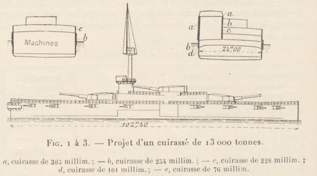
Now back to naval matters, in 1967 the Israeli destroyer Eliat was sunk by STYX anti-ship missiles. Previously it was assumed that long and medium range interception were sufficient. However, this incident encouraged development of new systems with much quicker reaction time and higher effectiveness.
General Dynamics proved eager to find a solution and started development on their Phalanx system. This married a search and tracking radar to a 20 mm M61 Vulcan rotary cannon with 4500 rounds per minute rate of fire. The US shared their interest in developing this project with her NATO allies. However, the Koninklijke Marine (Royal Dutch Navy) had certain reservations. They were under the impression that a better radar was available natively. The 3 cm / 8 mm radar was considered especially better for tracking of ‘sea skimmer’ missiles. Furthermore, the 20 mm calibre of the weapon was well studied to be insufficient for the task.
On the basis of the success of the mechanised air defence vehicle the Netherlands started studies on a lightweight version for ships under the AJAX-project. Canada and Germany joined the Netherlands in their research and it became a NATO group project on “Very Short-Range Air Defence Weapon for Ships” (VSRADWS). It was then evaluated along with the General Dynamics proposal. The outcome was disappointing. Both had shortcomings. The AJAX main detriment was the low fire rate, which at only 1100 rounds per minute was not enough to guarantee hits on target. The calibre of 35 mm was also deemed in excess as the 3 to 4 km range at which it would still provide potent enough was impractical from an accuracy standpoint. 30 mm calibre weapons proved more than effective, even 25 mm would marginally suffice in later studies.
To improve on the deficits of the AJAX, HSA started working with Emmerson Electric and Mauser on an autonomous integrated VSRADWS (CIWS). This would be the SEM-30 Goalkeeper. With four 30 mm Mauser type F machine guns the fire rate was increased to 3200 to 3600 rounds per minute. This design however met its end due to time and financial constraints.

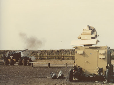
But in 1973 General Electric successfully evaluated their prototype GAU-8/A Gatling gun. This system, lightweight and capable of firing 4200 rounds per minute, proved an ideal solution. A shipborne prototype EX-83 was developed and revealed in 1975. HSA and General Electric subsequently came in contact and married the Flycatcher radar to the weapon. In November 1979 a demonstration named SHORTSTOP took place. Where the Koninklijke Marine, already aware of the Flycatcher performance, became equally impressed by the demonstrated weapon. The evolution of the previous SEM-30 was now inevitable. And the SGE-30 Goalkeeper was born.
Sources:
V. Esbach and E. Ferwerda, Goalkeeper “Het laatste redmiddel” (In dutch available here)
E.J. Keizer, PRTL, Pantser Rups tegen luchtdoelen
Staal, Hoe de Radar naar Hengelo kwam